Building obstacle avoiding robot is a simple & fun way to start learning arduino and electronics. A lot of useful articles explain this, but you will be blocked if you can’t get the same parts in your region. In this post, I’ll explain how to build a simple and minimal robot using the parts available online in India.
Watch the below video to get an idea of what you could build by following this article.
High level approach
We’ll be using a sensor to detect an obstacle in front of robot. Depending on the sensor input we’ll control the motor wheels of robot to either move forward or turn aside.
Prerequisites
- Arduino UNO or its clone
- HC-SR04 Ultra sonic sensor
- Robot chassis + 2 DC Motors with holder + 2 Wheels + 1 Castor Wheel + Screws & Nuts
- L293D motor driver
- Basic electronics kit contains breadboard, connecting wires, battery & other small useful items
- Jumper Wires: Male to Male, Male to Female
- Power source: 5V power bank or 5V battery pack (I used a phone charger power bank I had already)
- Tools: Screw driver, Scissor / Wire stripper
- Softwares: Arduino IDE
Steps
Follow the steps in the order below. If you get stuck at any point, refer to the troubleshooting section.
Step 1 : Get to know arduino and electronics basics
If you are new to arduino, try out few basic examples
- blinking led to learn controlling output
- push button to learn reading input & basic serial output for trouble shooting
- How to use breadboard (vertical power rails vs horizontal terminal strips)
Step 2: Connect ultrasonic sensor to detect obstacle
2.1: Connect the circuit as shown below

2.2: Add NewPing library to read distance.
- Download the NewPing library as zip here
- In Arduino IDE go to menu Sketch -> Include Library -> Add .ZIP as library -> Choose the downloaded zip file
2.3: Upload the below code to arduino
2.4: Test the distance measured by sensor
- In Arduino IDE go to menu Tools -> Serial Monitor
- Move an obstacle in front of sensor and test that correct distance is printed on serial monitor
Step 3: Assemble the robot chassis and test the motors & wheels
- The robot chassis needs to be assembled by looking at the images in purchased website. Bare minimum you should have the chassis base assembled with motors and wheels
- Cut 4 pieces of connecting wires each of length 15-20 centimeters and strip out both ends of the wire 1-2 centimeters
- Take 2 wires & connect one end of each wire to 2 connection slots of the motor. Repeat the same with other 2 wires using 2nd motor
- Take out a battery (it will be in basic electronics kit) and test motor wheel rotation by connecting other ends of the wires to battery
Step 4: Program L293D motor driver to control the wheels
4.1: Connect the L293D motor to arduino
I couldn’t get a fritzing diagram for this circuit since I don’t have the SVG for the part purchased. I’ll list the connections needed to get it running
- Connect 2 wires from one motor to 2 slots in M1 and other 2 wires from other motor to slots in M2
- Connect 5V and 12V on L293D to power line(Red) on breadboard
- Connect GND on L293D to GND line(Black) on breadboard
- Connect C1-A, C1-B on L293D to pins 2 & 3 respectively on arduino. These are motion control pins for Motor 1
- Connect C2-A, C2-B on L293D to pins 7 & 8 respectively on arduino. These are motion control pins for Motor 2
- Connect EN1 and EN2 on L293D to power line(Red) on breadboard. These are enable pins for Motor 1 and Motor 2 respectively. HIGH voltage(power) enables the motor and LOW voltage(GND) disables the motor
The connection should look somewhat like the image below
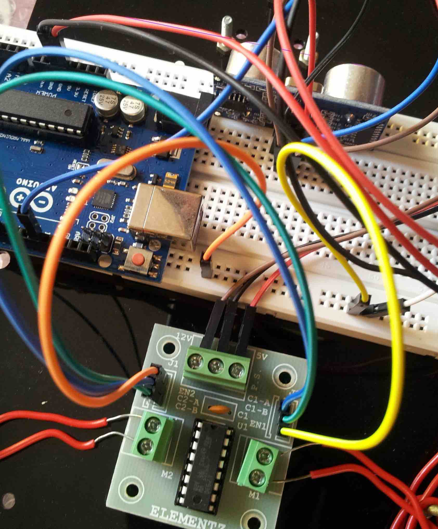
Please refer to images in purchased website for additional technical details
4.2: Upload the below code to arduino
4.2: Test the wheel movement control
- The
loopfunction initially tests themove_forwardfunction. Check both wheels are moving in forward direction. - If any of the motor wheels are rotating in wrong direction swap the connections in M1 or M2 depending on malfunctioning motor
- Change the line in
loopfunction to and replacemove_forwardwith other methods like drive_backward, turn_left, turn_right to test they work as expected
Step 5: Integrate sensor input to control the bot movement
Upload the below code which has logic to move the robot depending on distance of the obstacle. Feel free to change the obstacle distance or delay or the rotation angle as per your motor speed
Step 6: Test it in the field and celebrate!
- So far you would have used USB from your laptop as power source for arduino. Now you should use a power bank or 5V battery pack to test your robot in the field
- If everything works, run around…jump up & down…shout to the sky…any other way to celebrate the hard earned victory :)
Step 7: Enhancements
These are optional enhancements that I wanted to try but didn’t an opportunity to try
- The robot speed can be increased by connecting a 12V battery as power source for L293D
- The accuracy of obstacle detection can be increased by using couple of IR sensors at corners OR by using a servo to rotate the ultrasonic sensor for reading obstacles in the corners
- Attach leds, buzzers, laser, add a custom body to make it look like WALL-E or other funky stuff to add more jazziness the vehicle
- Send it to Mars or Do anything else you can imagine to save or end the human race
The code and fritzing diagram is also shared on github repo
Troubleshooting
- Double check the pin number you have connected to on arduino. You might have connected to to the wrong pin because of the angle at your are looking at these circuits. Count the pin numbers slowly to ensure you are connected to pin number x and not x + 1 or x - 1
- Double check the breadboard slots in which you have plugged in the wires or devices. Push the wires or devices to ensure they are plugged in firmly
- Test if the breadboard slots to which you have plugged-in works properly. Use a buzzer or other small equipments which can handle 5V to to test them out (Don’t use led without a resistor). I had an issue where some of the pin slots in in power rails were not working due to defective board
- Test the components such as wires, sensors, motors individually and ensure they work properly when used independently
- If nothing helps, google is your friend